Injection Mold Acceptance Standards: Complete Guide
Accepting an injection mold is one of the most critical steps in plastic product development. A poorly inspected mold leads to production delays, high reject rates, extra costs, and failed parts.
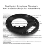
This guide provides full, industry-standard injection mold acceptance criteria used by professional mold makers and buyers worldwide. Use this checklist to verify your mold before final payment and production.
1. Mold Appearance Acceptance Standards
Nameplate & Markings
- Mold number, weight (KG), dimensions (mm) must be clearly labeled
- Characters: 1/8 inch, uppercase, neat arrangement
- Nameplate fixed on mold feet near rear template with 4 rivets
- DATUM mark on all plates: 5/16” height, 10mm from edge
- Component numbers on every plate
- Direction arrow + “UP” (yellow, 50mm height) for installation direction
Cooling Water Nozzles
- Size: G1/8″, G1/4″, G3/8″ (10mm pipe)
- Nozzle protrudes from mold base; recess ≤3mm
- Relief holes: φ25 / φ30 / φ35mm, chamfer ≥1.5×45°
- Marked IN1, OUT1 for water; G for air, O for oil
- External nozzles must have support pillars for protection
Mold Base & Structure
- No pits, rust, or unnecessary holes on mold frame
- All plates chamfered ≥1.5mm
- External parts (cylinders, water nozzles) protected by support legs
- Mold feet firmly fixed to mold base
Installation & Lifting
- Ejection hole matches injection machine; diameter 5–10mm larger than ejector rod
- Mold dimensions fit designated injection molding machine
- Molds over 8000KG use through bolts (not only press plates)
- Lifting holes available for parts ≥10KG
- Lifting rings can rotate 360° for balanced lifting
Locating Ring & Sprue Bushing
- Locating ring: φ100 / φ150mm, protrudes 10mm, fixed with 3×M6/M8 screws
- Installed in countersunk hole (not directly on plate surface)
- Sprue bushing R > injection machine nozzle R
- Sprue entrance diameter > nozzle injection diameter
Slides & Lifters
- Mandatory pre-reset mechanism if ejection interferes with sliders
- Oil cylinder core pulling & ejection controlled by travel switches
- Lifters removable through rear clamp plate holes
- Angle matches lifter design
General Appearance Items
- Oil distributor firmly fixed
- Standard rubber tubing & fittings for oil lines
- Ejector plate with stop pin
- Support pillar area: 25–30% of spacer block area
- Support pillar 0.05–0.15mm higher than mold legs
- Die locker ≥4 units (small molds ≥2)
- Three-plate molds: springs between top clamp plate & runner plate
2. Ejection, Return, Core Pulling & Demolding Standards
Ejection System
- Smooth ejection, no sticking or noise
- Lifters polished, 0.1–0.15mm lower than core surface
- Lifters with guide grooves (tin bronze), fixed by screws + dowel pins
- Ejector rod end: 0–0.1mm below core surface
- All ejector pins anti-rotation & numbered
- Ejector plate fully returns
- Ejection distance limited by stop block (45# steel)
Spring Standards
- Standard uncut, unground springs
- Installation hole diameter 5mm larger than spring
- Springs ≥φ20mm equipped with inner guide rod (10–15mm longer)
- Pre-compression: 10–15% of total length
- Color code: blue (light), yellow (lighter), red (heavy)
Slider & Lifter Rules
- Sliding components nitrided to HV700 (except ejector pins)
- Sliders have travel limits (springs, wave screws, or switches)
- Angle pin angle 2–3° less than lock block
- Slider sliding length ≥1.5× directional length
- Sliding distance ≥ core pulling distance +2–3mm
- Large sliders (>30KG) use T-slot with removable plates
- Oil cylinder core pulling with self-locking for thick-wall parts
3. Cold Runner System Standards
- Sprue inner surface polished to ▽1.6
- Runners polished to ▽3.2 or 320# oilstone
- Runner shape: trapezoidal or circular (three-plate molds)
- Gap: 10–12mm between top plate & runner stripper plate
- Gates & runners CNC machined (no manual grinding)
- Cold slug well at sprue front end
- No misalignment between cavity & core
4. Hot Runner System Acceptance Standards
- Neat wiring with clear wire numbers; easy maintenance
- Leakage & safety tests passed
- Temperature control ±2℃
- Heating rods fit gap ≤0.05–0.1mm (h7/g6)
- J-type thermocouples matching controller
- Air insulation layer: 25–40mm between manifold & mold plate
- No dead ends in melt flow
- Nozzles sealed with copper/aluminum rings (0.5mm higher)
- Thermal insulation between stripper plate & mold plate
- Nozzle orifice ≤φ5mm to avoid sink marks
- Wires protected, bundled, no exposure
- All circuits tested short-free before & after assembly
5. Packaging & Delivery Standards
- Cavity sprayed with anti-rust oil
- Sliding parts lubricated with grease
- Sprue bushing inlet sealed with grease
- Mold equipped with lock plates
- Full documents: drawings, BOM, manual, waterway diagram, spare parts list
- Exterior painted blue (or per customer request)
- Mold wrapped with film
- Wooden crate with clear label & direction mark
- Spare parts complete with supplier info
Conclusion
Following this injection mold acceptance standard checklist ensures you receive a safe, stable, production-ready mold that runs consistently for millions of cycles.
Always inspect before delivery to avoid disputes, rework, and hidden costs.
FAQ
When should I inspect a new injection mold?
Before final payment and before mass production.
What happens if a mold fails acceptance?
Require the mold maker to repair, modify, or rework until all standards are met.
What documents must a mold include?
2D/3D drawings, waterway diagram, parts list, material certificates, operation manual.
What is the standard mold base surface treatment?
Blue paint; all plates deburred and chamfered.