DFM for Plastic Products: The Ultimate Guide to Design for Manufacturing
Introduction
If you develop plastic parts for injection molding, you’ve almost certainly heard of DFM (Design for Manufacturing). Whether you work in automotive, electronics, medical devices, consumer goods, or aerospace, DFM isn’t just an engineering checkbox—it’s a proven framework to build high‑quality plastic products faster, cheaper, and more reliably.
In this guide, we break down everything you need to know about DFM for plastic products: what it is, why it matters, how to create a professional DFM report, key design rules, and the ongoing debate over who should own DFM in your workflow.
What Is DFM for Plastic Products?
DFM (Design for Manufacturability) means designing plastic parts with production, assembly, and moldability in mind from the very start of product development.
Core goals of plastic DFM:
- Verify process and mold feasibility before cutting steel
- Reduce manufacturing defects, rework, and delays
- Lower mold cost, material waste, and production expenses
- Improve part quality, consistency, and tool lifespan
- Shorten overall development cycles
In short: DFM turns good‑looking designs into producible parts.
Why DFM Is Critical for Plastic Injection Molding
Without a proper DFM review, you risk:
- Sink marks, warpage, short shots, and weld lines
- Stuck parts, ejection damage, and high reject rates
- Overly complex molds with slides, lifters, or side actions
- Delayed launches and blown project budgets
- Parts that look good on screen but fail in production
A strong DFM process eliminates these risks before mold fabrication begins.
Key Benefits of Plastic DFM
- Prevent manufacturing issues earlyCatch defects before they reach the shop floor, avoiding costly corrections later.
- Speed up developmentStreamline workflows, reduce iterations, and get to market faster.
- Optimize part design & qualityRefine wall thickness, draft, gates, and ejection for peak performance.
- Cut total costsReduce mold complexity, material use, cycle time, and scrap rates.
- Support eco‑friendly productionChoose compliant materials and reduce waste for greener manufacturing.
- Simulate real‑world moldingPair DFM with Moldflow to preview filling, cooling, and pressure behavior.
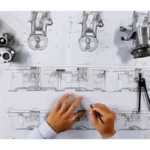
Traditional DFM Analysis Workflow for Plastic Parts
Most manufacturers follow this standard sequence:
- Product design finalized
- DFM analysis & report creation
- Design revisions based on DFM feedback
- Mold design and fabrication
- Injection molding production
This process is used in more than 98% of plastic product development workflows worldwide.
A complete DFM report covers:
- Shrinkage & material selection
- Mold steel and tooling layout
- Gate location & runner system (hot/cold)
- Wall thickness uniformity
- Draft angles
- Parting lines
- Ejection pin positions
- Surface finish & texture requirements
- Moldflow simulation (filling, weld lines, air traps)
How to Create a Professional DFM Report
A high‑quality DFM report reflects engineering skill and directly impacts mold cost and part quality. Below is the standard structure used by professional mold makers.
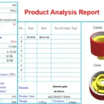
1. Basic Product & Mold Information
- Part name & number
- Plastic resin (ABS, PC, PP, PA, etc.)
- Shrinkage rate
- Cavity number
- Critical dimensions & tolerances
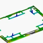
2. Product Design Overview
- 2D/3D part views
- Critical functional areas
- Cosmetic surfaces
3. Customer Requirements
- Surface finish (smooth, textured, matte, glossy)
- Appearance standards
- Assembly constraints
4. Injection Method & Gate Location
- Gate type (pin, edge, submarine, fan, hot runner)
- Gate position & size
- Runner layout
- Hot runner brand & system type
5. Draft Angle Analysis
- Verify draft on core & cavity sides
- Higher draft for textured or plated surfaces
- Prevent sticking and ejection damage
6. Parting Line Review
- Confirm parting line position
- Check for conflicts with cosmetics or function
- Minimize visible flash or lines
7. Ejection System Design
- Ejector pin size, number, and placement
- Balanced force distribution
- Avoid marks on cosmetic surfaces
8. Wall Thickness Check
- Ensure uniform thickness
- Highlight thick spots that cause sinks
- Suggest adjustments to eliminate defects
9. Problem Analysis & Solutions
- List potential defects
- Explain root causes
- Provide clear design fixes
- Show before/after revisions
10. Advanced Moldflow Analysis (Optional)
For complex parts:
- Fill time
- Weld line locations
- Air traps
- Pressure drop
- Temperature distribution
- Warpage prediction
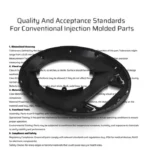
Essential DFM Design Rules for Plastic Parts
Follow these rules to create naturally moldable designs:
Wall Thickness
- Keep thickness consistent across the part
- Avoid sudden changes
- Typical range: 0.8 mm – 4.0 mm depending on resin
- Use ribs instead of thick walls for stiffness
Draft Angles
- Minimum 0.5°–1° for smooth surfaces
- 3°–5°+ for textured or deep walls
- Prevents tearing, sticking, and cosmetic damage
Gates
- Place gates away from cosmetic surfaces
- Size gates for balanced filling
- Use hot runners for high‑volume or sensitive parts
Corners
- Add radii to eliminate stress concentrations
- Improves flow and strength
- Reduces mold wear
Undercuts
- Minimize or eliminate undercuts
- Use slides/lifters only when necessary
- Design snap fits “in line of draw”
Bosses & Ribs
- Rib thickness = 60% of main wall
- Connect bosses with gussets
- Prevent sink marks and voids
Who Should Do DFM? Product Designers vs. Mold Engineers
A major industry debate:
Should DFM be done by product designers or mold makers?
Argument 1: Mold designers should own DFM
- They understand molds and injection best
- Specialists should handle specialized work
- Most factories follow this model
Argument 2: Product designers should own DFM
- Manufacturers prioritize profit over cost reduction
- Early DFM prevents late, costly changes
- Design‑side DFM balances function, aesthetics, and cost
- Shortens development cycles by avoiding rework
Our View
DFM is a mindset, not just a task. It should be embedded from concept to production.
- Mold teams provide critical manufacturing insights
- Product teams ensure performance, appearance, and cost targets
- Collaboration = best results
Conclusion
DFM for plastic products is one of the most impactful steps you can take to reduce cost, speed up development, and improve quality. Whether you’re designing a small connector or a large automotive component, a thorough DFM review before mold start will save you time, money, and frustration.
By following standard DFM structure and design rules, you create parts that mold reliably, look great, and perform consistently.
FAQ
What does DFM stand for?
Design for Manufacturing (or Design for Manufacturability).
When should I perform DFM?
As early as possible — ideally during initial concept design, definitely before mold design.
How long does a DFM report take?
Simple parts: a few hours. Complex parts: 1–3 days including Moldflow.
Do I need software to do DFM?
Yes — CAD (UG, SolidWorks), simulation tools, and presentation software (PPT).
Would you like me to turn this article into a Google-friendly blog template with H1–H6 structure, keyword placement, and ready-to-use meta title/description?